Introduction to the Visual Effect Graph
In this Visual Effect Graph tutorial, you’ll learn how to easily create complex visual effects in Unity with a node editor. By Harrison Hutcheon.
If you have any experience with Unity, you’ve likely used its Particle System component to add particle effects to a project.
Particle effects are a great way to add polish to interactive experiences. Unity’s Particle System makes adding and customizing particle effects simple and straightforward.
Unfortunately, intricate particle effects can affect a game’s performance, limiting the types of simulations you can create.
This is where the Visual Effect Graph comes in. It allows for complex simulations using millions of particles. Yes, you read that right: millions of particles! Its feature-rich visual interface makes it easy to create and experiment with stunning particle effects.
In this tutorial, you’ll explore some of the endless possibilities offered by Unity’s Visual Effect graph.
Getting Started
This tutorial uses Unity version 2019.3. If you haven’t installed this version of Unity, you can use Unity Hub to install and manage multiple Unity versions across your projects.
Use the Download Materials button at the top or bottom of the tutorial to download the starter and final projects. Extract them, then open the IntroVFXGraph Starter project using the Unity Editor.
Take a look at Assets/RW. Here you’ll see your project folders. The main focus will be on:
- Prefabs: Find your pre-built GameObjects here.
- VFX: You’ll store the Visual Effect Graphs you create here.
- Scripts: Here, you’ll find custom scripts.
- Scenes: Contains the main game scene.
Double-click the scene file MainScene in RW/Scenes, to open it. Next, press Play to see the project in action.
You’ll see a castle with towers you can select. The UI has four Tower Upgrade buttons and three counters to track materials in the top-left corner.
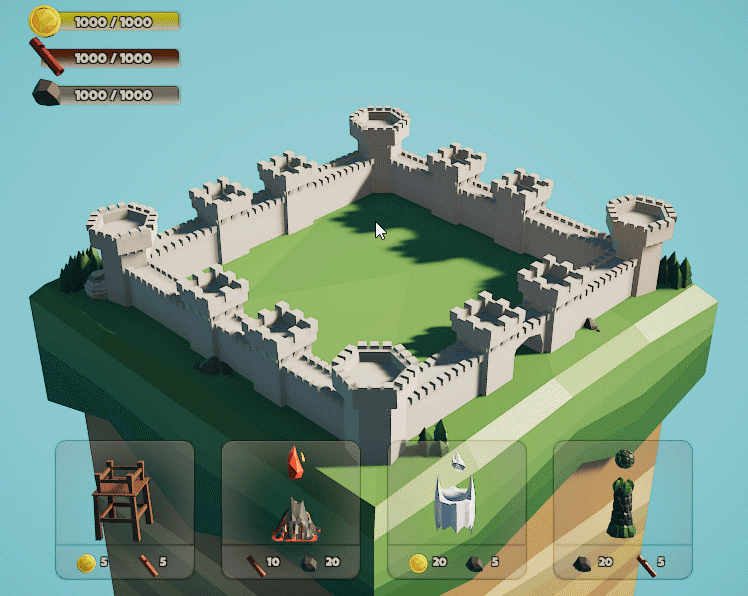
Selecting a tower and clicking an upgrade triggers an animation that pools the necessary resources in the middle of the screen.

When the resources have finished pooling, they disappear and the selected upgrade appears on the tower. Once you’ve upgraded a few towers, stop the playback.

The goal of this tutorial is to spice up the upgrade process with some cool visual effects, making it more interesting and engaging.
The first step toward this goal is to understand the Visual Effect Graph, what it’s capable of and its workflow.
What Is the Visual Effect Graph?
The Visual Effect Graph is a specialized tool that allows you to create complex visual effects using an intuitive visual interface.
This tool, along with the Visual Effect object you’ll add to your scene, work much like the particle system.
You can configure properties over the lifetime of a particle, how the particle is rendered and which forces act on each particle.
The main difference between the two systems stems from the hardware used to simulate the effect. The particle system uses the CPU, while the Visual Effect Graph uses the GPU.

This difference is important because the GPU is designed to perform many small mathematical operations at the same time. You need this ability to render graphics. As it turns out, this also makes the GPU ideal for handling the mathematics behind complex visual effects.
However, even with the power of the GPU behind it, the VFX Graph is not always an effective substitute for the particle system.
Here are a few key differences to keep in mind when trying to decide which system is right for your project:
- VFX particles aren’t affected by the physics engine, only by physical forces specified in the graph. This means that VFX particles won’t collide with physics objects or respond to global settings like gravity.
- Controlling a visual effect with scripts is more difficult — but not impossible!
- The VFX graph runs on the High Definition Render Pipeline (or HDRP), which requires a higher-end GPU. It’s not ideal for low-end PCs or mobile devices.
Now, it’s time to take your first look at the Visual Effect Graph by creating one and exploring its features.
Exploring the VFX Graph
Create a Visual Effect Graph in the RW/VFX project folder by right-clicking and selecting Create ▸ Visual Effects ▸ Visual Effect Graph. Name the new Visual Effect Burst, because you’ll use this graph to create a burst effect later in the tutorial.
Double-click Burst to open the VFX Graph editor. It should look like this:

This interface uses a system of nodes and blocks to construct the order of operations of a visual effect and to perform calculations to manipulate particle properties.
There are currently four context nodes, or contexts for short.
Each context contains blocks, which define particle properties during specific steps in the simulation. The steps execute in the order they’re listed. Blocks are specific to their context. That means, for example, you can’t add a spawn rate block to an Update or Output context.
To the side of your graph, there’s an empty box called the Blackboard, which is labeled with the name of your Visual Effect, Burst. The Blackboard stores references to variables that you can use throughout a Visual Effect Graph. This is useful when building a complicated graph that uses a specific value in many different calculations.

You can also expose these variables to the editor and to C# scripts, which allows you to manipulate the Visual Effect during the game’s runtime.
With all this in mind, here’s a quick breakdown of what’s currently in the project:


The Output Particle Quad is one of many output contexts that allow you to render particles in many forms, even as primitive 3D objects. In this context, you orient the particles to face the main camera. Their color and size will change over the lifetime of each particle.
- The Spawn Context: The first step of the simulation, which spawns the particles. It includes blocks such as Constant Spawn Rate, Periodic Burst and Single Burst.
- The Initialize Particle Context: Sets the initial state of the particles such as lifetime, initial position and initial velocity. Currently, the particles have a random upward velocity and a random lifetime between 1 and 3.
- The Update Particle Context: Handles updates to particles that occur over time including color, size and which physical forces act on each particle.
-
The Output Particle Quad Context: Controls the rendering of the particles. In this case, the particles render as quads, which are flat, square sprites.
The Output Particle Quad is one of many output contexts that allow you to render particles in many forms, even as primitive 3D objects. In this context, you orient the particles to face the main camera. Their color and size will change over the lifetime of each particle.
You may have noticed that there are no other nodes in the default VFX Graph template. For simple effects, extra nodes outside of the contexts aren’t always necessary. When you build your two visual effects, you’ll get a better idea of how you can use each approach.