Arduino Tutorial: Temperature Sensor
An Arduino Tutorial on building a temperature sensor – and an iPhone app to connect with it! By Tony Dahbura.
Installing the Libraries
While you’re waiting for the last package to arrive in the mail, you can install the various libraries you’ll need to talk to the shields. The Arduino IDE already includes the libraries for communicating with the Ethernet Shield.
The temperature sensors need a library for the 1-Wire portion, and Dallas Semiconductor has some useful routines specifically for the probes. These libraries are all in the tutorial download in the folder Arduino_Libraries.
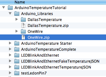
To install the libraries, first find the Arduino_Libraries folder in the resources you downloaded earlier and double click both files to unzip them into folders:
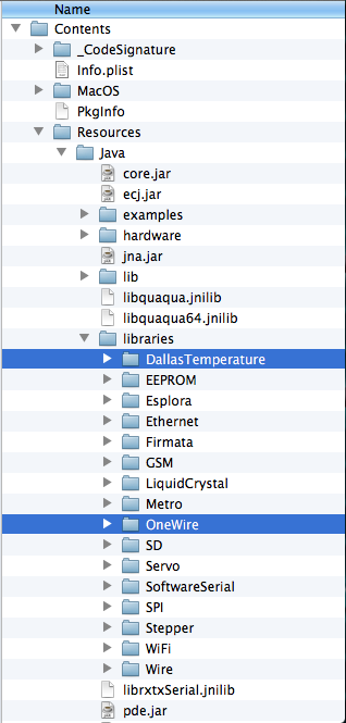
Then select the icon for the SDK and Show Package Contents. The window will display a folder called Contents. Install the DallasTemperature and OneWire folders in the Contents/Resources/Java/libraries folder, as shown:
If you had the Arduino IDE open, Quit and restart to have it load the new libraries. That’s it! Check to see if they’ve loaded successfully by going to File/Examples and looking for DallasTemperature and OneWire in the menu.

At this point you should have all your gear in place. Now it’s time to do some wiring!
Wiring It All Together
Before you move on to the temperature sensor, you are going to do some basic setup to get a LED blinking. If you’ve already done the Electronics for iPhone Developers tutorial series, this will be review – but don’t worry, you’ll get to the fun new stuff soon!
First, if you haven’t already, assemble the Arduino UNO and breadboard based on instructions that come with the Sparkfun Inventor’s Kit.
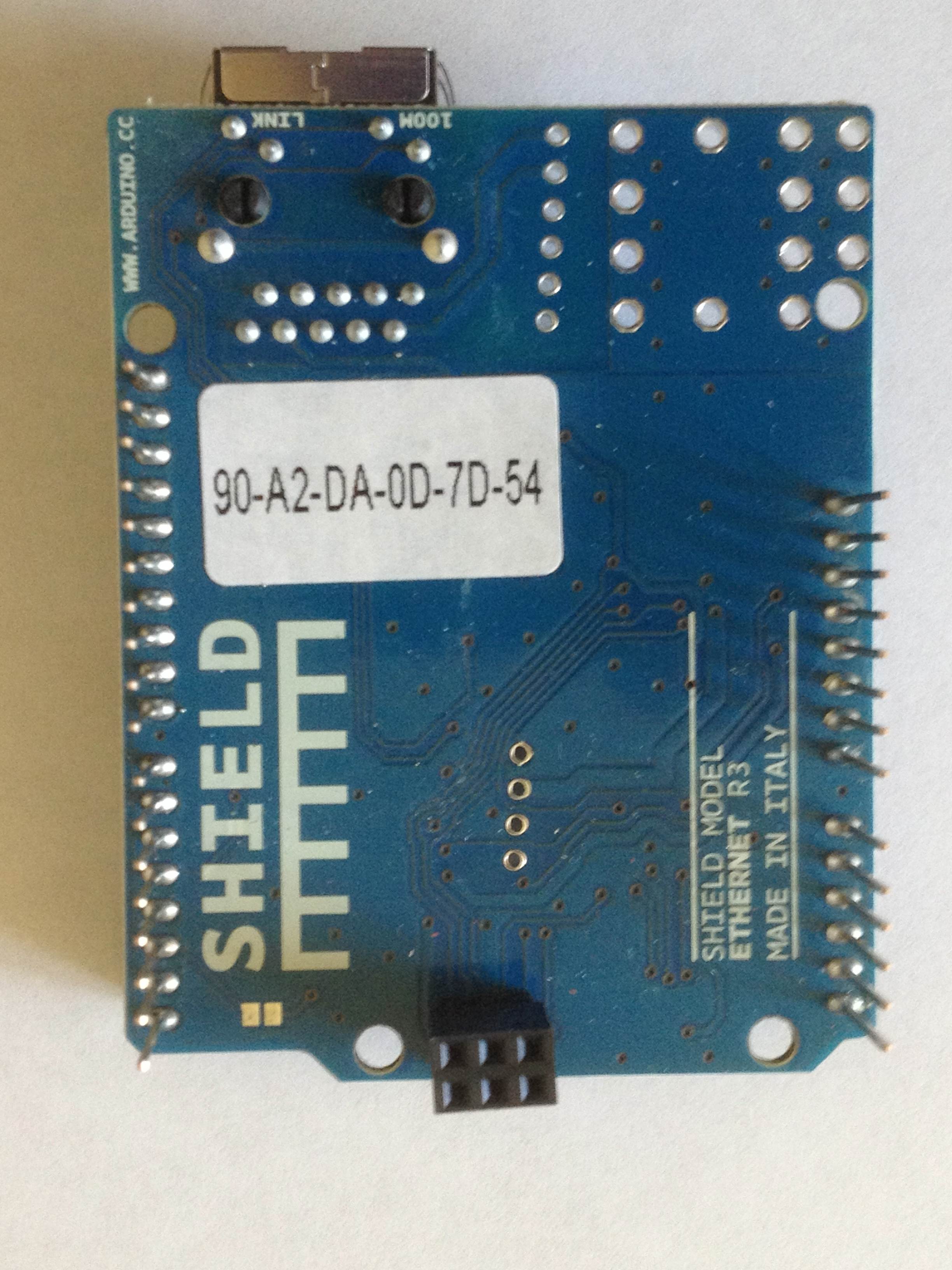
Next, prior to installing the Ethernet Shield, look on the bottom of the board for the MAC address and write it down, as you’ll need to include it in the code you write to control the interface.
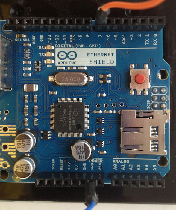
Then plug the Ethernet Shield into the header pins on the ARduino board. Note that there are six pins on the back of the Ethernet Shield that also connect to the UNO board. Slide the board into place carefully and the Ethernet jack should be above the USB connector when installed.
Now you will wire in the LED as a status indicator. Besides, what’s an electronics project without some blinking LEDs?
I’ll give the instructions first, then explain the theory afterwards:
- Connect a blue wire to one of the connectors in the blue row on the breadboard.
- Connect an orange wire to row J, column 16 on your breadboard.
- Connect a 330-ohm resistor (orange/orange/brown) to row J, column 17. Connect the other end of the resistor in the blue row for column J.
- Connect the longer lead (+) of a green LED to row F, column 16 and the shorter lead (-) to row F, column 17.
Once you’ve completed the above, your breadboard should look like this:

Now connect the free ends of the blue and orange wires to the Ethernet Shield:
- Connect the free end of the blue wire to the GND connector/header on the Ethernet Shield.
- Connect the free end of the orange wire to the header labeled 7 on the Ethernet Shield.
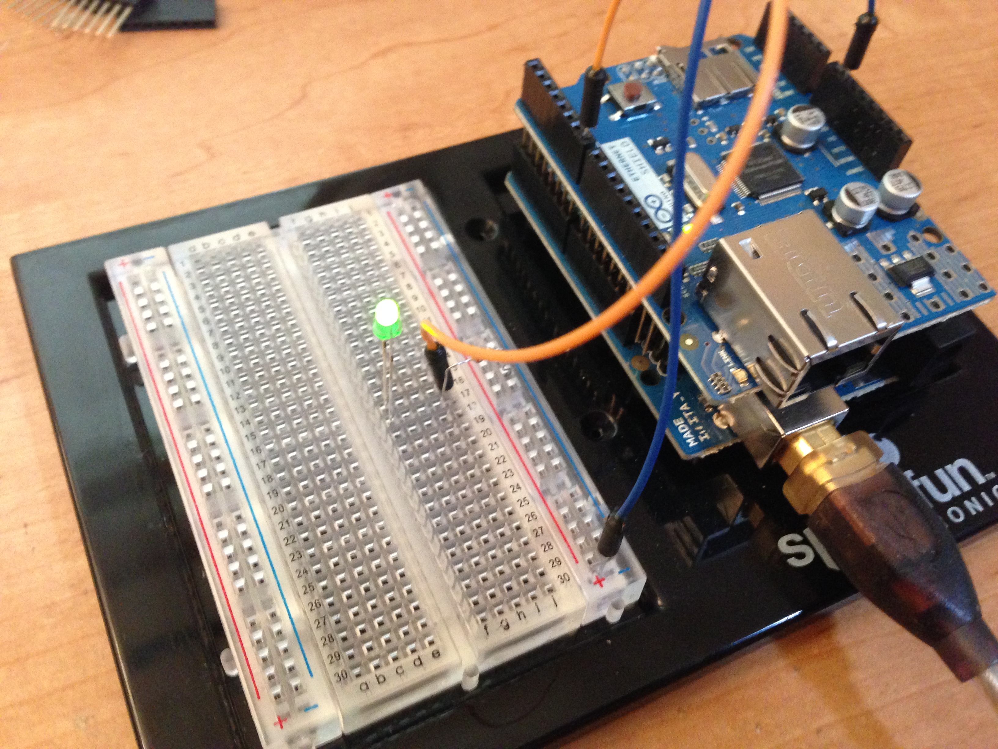
Now your Ethernet Shield should look like this:
You’ve just built a simple switch circuit, except the switch is a computer pin! By toggling the D7 data line between high and low, you will turn the LED on and off, respectively.
You’ve wired the ground lead of the LED to the ground of the whole circuit with a small resistor (330 ohms) to reduce voltage to the LED. The positive side of the LED is wired to the D7 pin of the computer chip. This pin can be controlled via software to have a high value of 5 volts or a low value of 0 volts. As you’ll see shortly, when D7 is set to high, the LED will light.
In my circuit I used a green LED that I had in my box of spare parts. The color does not matter, just choose an LED that you like the color. In the inventor’s kit from SparkFun you get red and yellow LEDs. Just choose either one!
Check your wiring to be sure all is securely fastened. Then connect one end of the USB cable into the lower connector and the other end into your Mac computer. You should see a green indicator on the shield light indicating that the system has power.
Launch the Arduino SDK by double-clicking it. You should see a blank window open for you to create a sketch, which is Arduino-speak for a program.
Wiring the LED onto the Breadboard
First things first: test your LED by making it blink.
Enter the following code into the blank editor window:
const int ledPin = 7;

void setup(void)
{
  pinMode(ledPin, OUTPUT);
}

void loop(void)
{
  digitalWrite(ledPin, HIGH);
  delay(1000);
  digitalWrite(ledPin, LOW);
  delay(1000);

}
The Arduino system software is designed to run the code in setup() every time the circuit reboots – that is, every time power is removed and restored, or the reset button is pressed. At the conclusion of setup(), the chip repeatedly calls loop().
The code in setup() marks ledPin (data pin 7) as an output pin, meaning you want it to set values rather than read values. You then tell the chip to repeatedly execute the loop, which sets the pin to high (thereby giving it a value of 5 volts), delays for 1000 milliseconds (1 second), then sets the pin to low, delays and repeats.
After you’ve entered this code, select File/Upload.
If you get an error, go to Tools/Serial Port and make sure /dev/tty.usbmodemfd131 is selected and not some other /dev device. The Arduino connects as a serial device via USB. Secondly, check that your Tools/Board choice is set to Uno.
If your uploading of this test program is successful, the LED will turn on and off repeatedly once a second.
Hooray! Your LED is now wired into the circuit. You will use this LED to convey status information as your temperature-monitoring system comes online.
Save this sketch as TestLEDOnPin7. You’ll use this little program to test your LED wiring, like a mini hardware unit test!
Your circuit will use more input/output pins than other tutorials you may have read in the past. Because of the large number of pins, it’s good practice to map out in advance which pins you’ll use for what. Here’s a summary:
- Data pin 5: temperature sensor 1 (indoor)
- Data pin 6: temperature sensor 2 (outdoor)
- Data pin 7: status LED (currently connected)
- Data pins 10-13: Ethernet Shield