Arduino Tutorial: Temperature Sensor
An Arduino Tutorial on building a temperature sensor – and an iPhone app to connect with it! By Tony Dahbura.
Monitor the temperature around you from your iPhone!

Monitor the temperature around you from your iPhone!
If you’re like me, every morning before you leave for work you wonder whether you should wear a jacket before heading outside. You might not have time to check outside your front door, but you always have time to check your iPhone! :]
The problem is, standard weather apps tell you about the temperature in a nearby city or suburb – but not necessarily about extremely local conditions. And what about that aquarium you would like to monitor, or your mini indoor greenhouse?
This is a job for the latest open source microcontroller – the Arduino.
In this tutorial, you’ll build an Arduino project for the iPhone that lets you connect multiple temperature probes you can place in different locations and query for their readings.
Keep reading to learn more about the Arduino, find out what materials you’ll need for this tutorial, and finally – build your own networked temperature-monitoring station!
This tutorial assumes you have been through some of the earlier tutorials on the Arduino. If not, you may want to check out our beginner Electronics for iPhone Developers tutorial series before starting.
What You’ll Need
This tutorial requires some specific hardware components to interface with the temperature probes. You’ll be making use of a microcontroller (the Arduino), an Ethernet interface, and connecting status and temperature probes. If you’ve completed other Arduino tutorials on the site, you should have some of these parts – and as a budding electronics hobbyist, now is your chance to begin a collection of reusable modules!

The full parts list of required components is below, with URLs to purchase them. The total cost of all the parts is approximately $160 USD. If this seems like a lot of money, remember that you are stocking yourself with plenty of components that you can tinker with beyond this tutorial. If you’ve done previous tutorials, then you already have an Inventor’s Kit and maybe the Ethernet Shield, which drops the total price to $38.00.
For the cheaper components, it makes sense to order a few extra to have around and use for other projects you may want to do.
The Parts
If you already have various breadboards, USB cables, resistors and LEDs, then you can just buy the Arduino Uno Board DEV-11021 at $29.95 (Quantity 1). Though the inventor’s kit above is still a great buy, just to have a toolbox of spare parts!


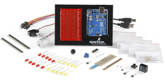
- SparkFun Inventor’s Kit for Arduino KIT-11227 at $94.95 (Quantity 1). This is the most expensive item but includes a lot of parts for later use, as well as a prototype breadboard. Remember from the Electronics for iPhone Developers tutorial series that a breadboard is just a simple way to connect wires together – the red area in the screenshot below
-
Arduino Ethernet Wiz Shield DEV-09026 at $45.95 (Quantity 1).

-
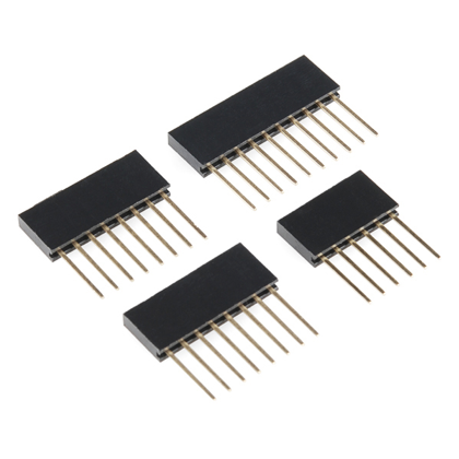
Arduino Stackable Header Kit – R3 at $1.50 each. (Quantity 2, but more won’t hurt your parts bin!)

-
Temperature Sensor, also available direct from Seeed Studio, at $12.50 each. (Quantity 2, but more are nicer in case you want to expand your project later.)

-
Grove Shield Interface Board, also available direct from Seeed Studio, at $10.00 (Quantity 1).

- A port available on your network switch or router, and an Ethernet cable to connect it to. You probably have these already, but I just wanted to give you a heads up so you can be sure to locate yourself in the same room as your switch or router as you work on this tutorial – or have a very long cable! :]
If you already have various breadboards, USB cables, resistors and LEDs, then you can just buy the Arduino Uno Board DEV-11021 at $29.95 (Quantity 1). Though the inventor’s kit above is still a great buy, just to have a toolbox of spare parts!
Once you’ve gathered your parts together, let’s get started!
Installing the Arduino IDE
Next you need to install the Arduino Integrated Development Environment if you haven’t already. The IDE is available at http://arduino.cc/en/main/software. Download the appropriate version for your platform, Mac OS X of course!
Install the IDE by unzipping the file and placing it in your Applications folder. The IDE does require Java, so if you don’t have Java installed, open a Terminal window and type java -version to have your Mac prompt to install the language.
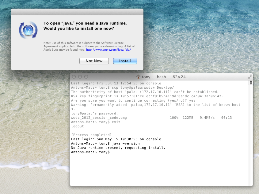
A couple of seconds later, you’ll see a dialog on your screen asking if you want to download and install Java. Click the Install button.
Lastly, download the software components for this tutorial from here. The zip file includes various libraries you’ll need and a starter iPhone project for later.
While waiting for your parts to arrive, let’s discuss a bit of the theory behind what you’ll build, including the general principles behind the electronics.
A Little Electronics Theory
If you want to skip the electronics theory and get right to building, click here.
Your project will make use of Arduino shields. Shields are special boards you can purchase that support a specific function, analogous to classes when building a program.
The Ethernet Shield contains the necessary hardware to connect to an Ethernet network. It also includes all the software you need to encode and decode the electrical signals that allow devices on an Ethernet network to communicate.
The Grove Shield brings a bunch of connectors to the board, allowing you to plug in many different sensors using one common connector. Alternatively, you could wire your sensors directly to the breadboard, but these connectors ensure you don’t plug the wrong wires into the wrong pins and keep things looking neat. Seeed Studio makes many other Grove connectors that you can try out once you get the hang of working with the Arduino.
When connecting devices to a microcontroller, you need to use data pins.
The Arduino has a series of digital pins that can be set to high or low and programmed for input or output modes. Setting a pin to output mode causes a connected device to receive 5 volts when high and 0 volts when low. Setting the pin to input mode allows you to read the value as high or low, depending on whether it has 5 volts or 0 volts (otherwise called ground) set on it.
Here’s a diagram of the pins on an Arduino (don’t worry about the details for now):

While this might seem like a lot of data pins, some are reserved for certain uses, while others are taken up by the shields. The Ethernet Shield, for instance, uses digital pins 10,11,12,13 (chip pin numbers 16-19). Full technical details for the Ethernet Shield are here. Various boards will commandeer various pins, so there’s only certain pins reserved for your use.
Your temperature probe uses a technology called 1-Wire bus. This technology is a bus system originally designed by Dallas Semiconductor that allows multiple devices to reside on a single data pin. The bus has a single master – the Arduino – and various workers that each sit on the bus and are identified by their own unique 64-bit serial number.
Using 1-Wire bus, each digital pin can support up to 255 devices! For more on 1-Wire bus, see this wiki page.

Your temperature probe is actually a unique device on this 1-Wire bus. It is called 1-Wire because a single wire is used to talk to all the devices on the bus – hence using only one pin of your choosing, labeled DQ in the image to the right.
Because you are using only two sensors, you will connect each to a different digital pin. If you wanted to wire 10-20 sensors together then you would connect them as depicted, requiring some soldering and shielded cables. Because you are only using two of them, you will just wire them to two dedicated digital pins. The use of the Shield Interface board makes this very easy. Even though you are only using one sensor per digital pin, the sensors still communicate via the 1-Wire bus communications protocol. Relax – there is a library to handle all the timing for you!


You will also a wire a light-emitting diode (LED) into the breadboard to act as a signal/status indicator.
LEDs are designed with positive (longer) and negative (shorter) leads. You’ll connect the negative lead to your common ground for the whole circuit (remember, ground is one of the pins on your Arduino). To power and control the LED, you’ll connect the positive lead to a digital pin. The negative lead will connect to a ground by way of a resistor (the resistor prevents too much electricity (voltage) from getting through and burning out the LED).
To turn the LED on and off, you’ll set the digital pin connected to the positive lead as an output pin. Setting this pin to high in code will turn on the LED, while setting it to low will turn it off. To blink the LED, you’ll simply turn it on and off with a delay.
The diagram below shows your wiring. The shorter ground lead of the LED is connected to the common ground, and the longer positive lead of the LED is connected to data pin 6.

The value of the resistor you use depends upon how much voltage you want to pass through the LED. The smaller the value, the brighter the LED and vice-versa. The Electronics for iPhone Developers tutorial series covers how to calculate the value of this resistor.
OK, enough theory! Let’s get back to building your temperature-monitoring station.