OpenGL ES Pixel Shaders Tutorial
In this OpenGL ES pixel shaders tutorial, take a deep dive into GLSL and fragment shader math – including how to make gradients and random noise! By Ricardo Rendon Cepeda.
Pixel Shader Geometry
In this section, you’ll learn how to use math to draw simple shapes, starting with a 2D disc/circle and finishing with a 3D sphere.
Geometry: 2D Disc
Open RWTSphere.fsh and add the following lines just below precision:
// Uniforms
uniform vec2 uResolution;
This is the same uniform encountered in the previous section and it’s all you’ll need to generate static geometry. To create a disc, add the following lines inside main(void):
// 1
vec2 center = vec2(uResolution.x/2., uResolution.y/2.);

// 2
float radius = uResolution.x/2.;

// 3
vec2 position = gl_FragCoord.xy - center;

// 4
if (length(position) > radius) {
  gl_FragColor = vec4(vec3(0.), 1.);
} else {
  gl_FragColor = vec4(vec3(1.), 1.);
}
There’s a bit of math here and here are the explanations of what’s happening:
- The
centerof your disc will be located exactly in the center of your screen. - The
radiusof your disc will be half the width of your screen. -
positionis defined by the coordinates of the current pixel, offset by the disc center. Think of it as a vector pointing from the center of the disk to the position. -
length()calculates the length of a vector, which in this case is defined by the Pythagorean Theorem√(position.x²+position.y²).- If the resulting value is greater than
radius, then that particular pixel lies outside the disc area and you color it black. - Otherwise, that particular pixel lies within the disc and you color it white.
- If the resulting value is greater than
- If the resulting value is greater than
radius, then that particular pixel lies outside the disc area and you color it black. - Otherwise, that particular pixel lies within the disc and you color it white.
For an explanation of this behavior, look to the circle equation defined as: (x-a)²+(y-b)² = r². Note that r is the radius, ab is the center and xy is the set of all points on the circle.
Since a disc is the region in a plane bounded by a circle, the if-else statement will accurately draw a disc in space!
Before you build and run, change your program’s fragment shader source to RWTSphere in RWTViewController.m:
self.shader = [[RWTBaseShader alloc] initWithVertexShader:@"RWTBase" fragmentShader:@"RWTSphere"];
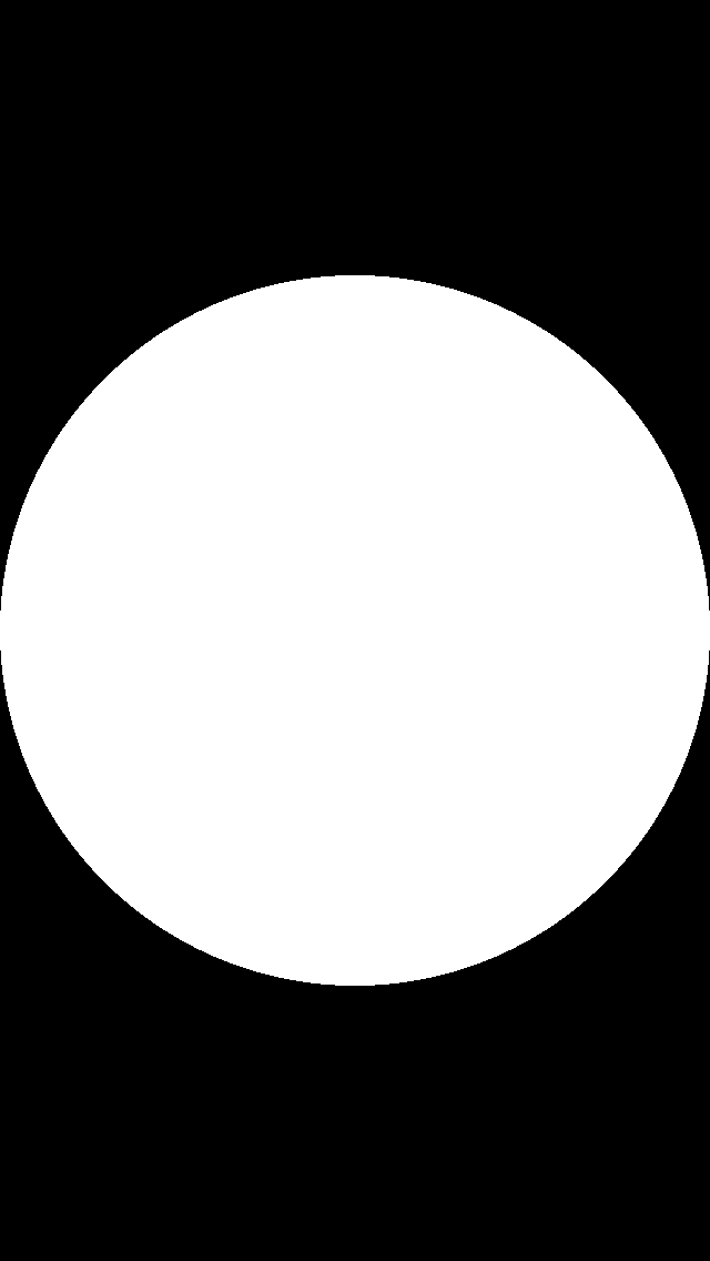
Now, build and run. Your screen should show a solid white disc with a black background. No, it’s not the most innovative design, but you have to start somewhere.
Feel free to play around with some of the disc’s properties and see how modifications affect your rendering. For an added challenge, see if you can make the circle shape shown below:
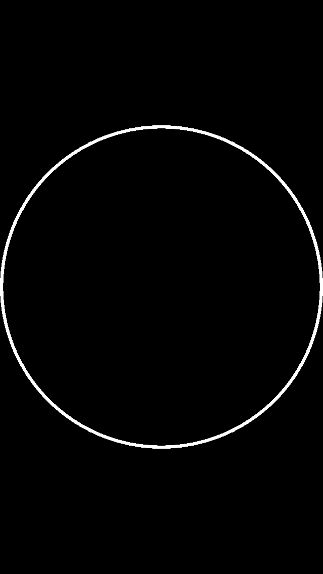
Hint: Try creating a new variable called thickness defined by your radius and used in your if-else conditional.
[spoiler title="Skinny Circle"]
vec2 center = vec2(uResolution.x/2., uResolution.y/2.);
float radius = uResolution.x/2.;
vec2 position = gl_FragCoord.xy - center;
float thickness = radius/50.;

if ((length(position) > radius) || (length(position) < radius-thickness)) {
  gl_FragColor = vec4(vec3(0.), 1.);
} else {
  gl_FragColor = vec4(vec3(1.), 1.);
}
[/spoiler]
If you attempted the challenge or modified your GLSL code, please revert back to that basic solid white disc for now (Kudos for your curiosity though!).
Replace your if-else conditional with the following:
if (length(position) > radius) {
  discard;
}

gl_FragColor = vec4(vec3(1.), 1.);
Dear reader, please let me introduce you to discard. discard is a fragment-exclusive keyword that effectively tells OpenGL ES to discard the current fragment and ignore it in the following stages of the rendering pipeline. Build and run to see the screen below:

In pixel shader terminology, discard returns an empty pixel that isn’t written to the screen. Therefore, glClearColor() determines the actual screen pixel in its place.
From this point on, when you see a bright red pixel, it means discard is working properly. But you should still be wary of a full red screen, as it means something in the code is not right.
Geometry: 3D Sphere
Now it's time to put a new spin on things and convert that drab 2D disc to a 3D sphere, and to do that you need to account for depth.
In a typical vertex+fragment shader program, this would be simple. The vertex shader could handle 3D geometry input and pass along any information necessary to the fragment shader. However, when working with pixel shaders you only have a 2D plane on which to "paint", so you'll need to fake depth by inferring z values.
Several paragraphs ago you created a disc by coloring any pixels inside a circle defined by:
(x-a)²+(y-b)² = r²
Extending this to the sphere equation is very easy, like so:
(x-a)²+(y-b)²+(z-c)² = r²
c is the z center of the sphere. Since the circle center ab offsets your 2D coordinatesand your new sphere will lie on the z origin, this equation can be simplified to:
x²+y²+z² = r²
Solving for z results in the equation:
z² = √(r²-x²-y²)
And that’s how you can infer a z value for all fragments, based on their unique position! Luckily enough, this is very easy to code in GLSL. Add the following lines to RWTSphere.fsh just before gl_FragColor:
float z = sqrt(radius*radius - position.x*position.x - position.y*position.y);
z /= radius;
The first line calculates z as per your reduced equation, and the second divides by the sphere radius to contain the range between 0.0 and 1.0.
In order to visualize your sphere’s depth, replace your current gl_FragColor line with the following:
gl_FragColor = vec4(vec3(z), 1.);
Build and run to see your flat disc now has a third dimension.

Since positive z-values are directed outwards from the screen towards the viewer, the closest points on the sphere are white (middle) while the furthest points are black (edges).
Naturally, any points in between are part of a smooth, gray gradient. This piece of code is a quick and easy way to visualize depth, but it ignores the xy values of the sphere. If this shape were to rotate or sit alongside other objects, you couldn’t tell which way is up/down or left/right.
Replace the line:
z /= radius;
With:
vec3 normal = normalize(vec3(position.x, position.y, z));
A better way to visualize orientation in 3D space is with the use of normals. In this example, normals are vectors perpendicular to the surface of your sphere. For any given point, a normal defines the direction that point faces.
In the case of this sphere, calculating the normal for each point is easy. We already have a vector (position) that points from the center of the sphere to the current point, as well as its z value. This vector doubles as the direction the point is facing, or the normal.
If you’ve worked through some of our previous OpenGL ES tutorials, you know that it's also generally a good idea to normalize() vectors, in order to simplify future calculations (particularly for lighting).
Normalized normals lie within the range -1.0 ≤ n ≤ 1.0, while pixel color channels lie within the range 0.0 ≤ c ≤ 1.0. In order to visualize your sphere’s normals properly, define a normal n to color c conversion like so:
-1.0 ≤ n ≤ 1.0
(-1.0+1.0) ≤ (n+1.0) ≤ (1.0+1.0)
0.0 ≤ (n+1.0) ≤ 2.0
0.0/2.0 ≤ (n+1.0)/2.0 ≤ 2.0/2.0
0.0 ≤ (n+1.0)/2.0 ≤ 1.0
0.0 ≤ c ≤ 1.0
c = (n+1.0)/2.0
Voilà! It's just that simple
Now, replace the line:
gl_FragColor = vec4(vec3(z), 1.);
With:
gl_FragColor = vec4((normal+1.)/2., 1.);
Then build and run. Prepare to feast your eyes on the round rainbow below:

This might seem confusing at first, particularly when your previous sphere rendered so smoothly, but there is a lot of valuable information hidden within these colors…
What you're seeing now is essentially a normal map of your sphere. In a normal map, rgb colors represent surface normals which correspond to actual xyz coordinates, respectively. Take a look at the following diagram:
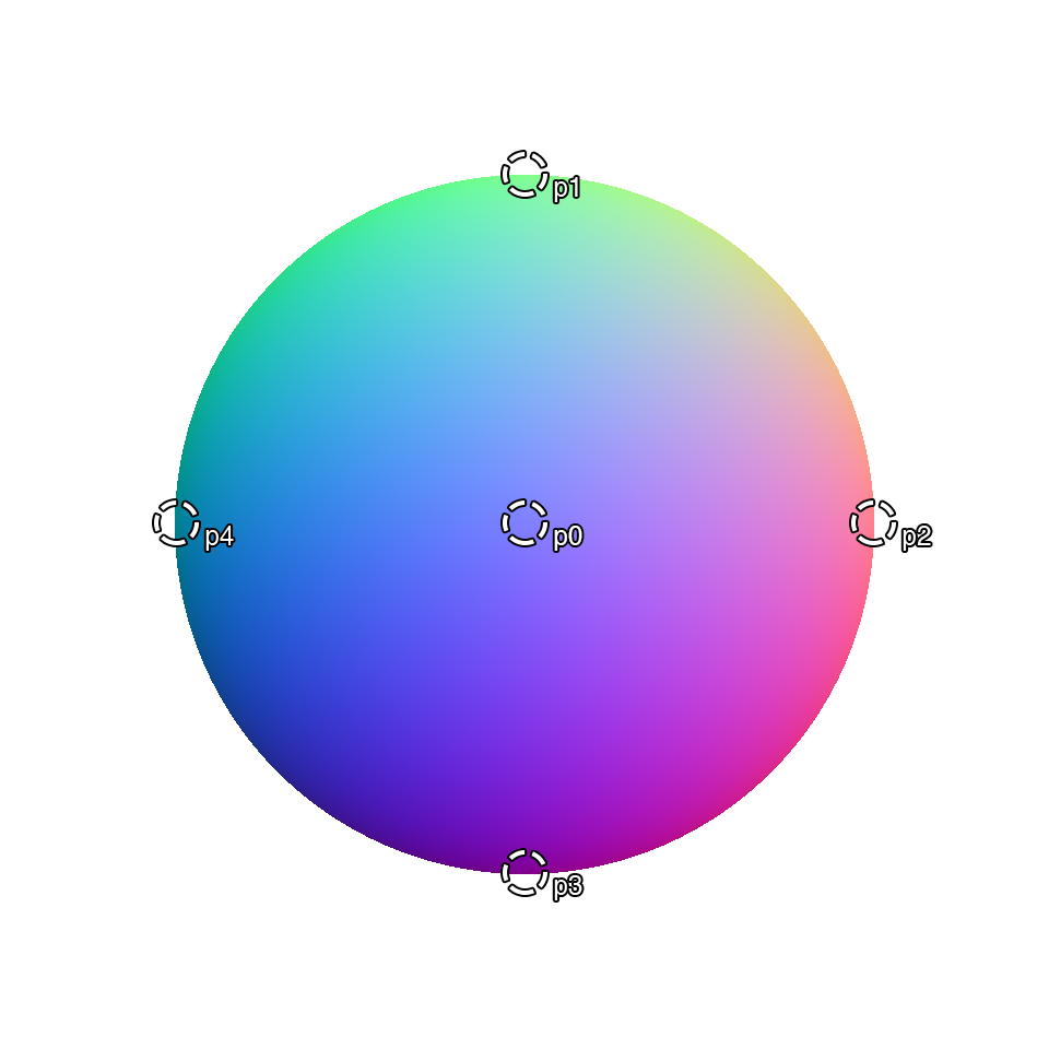
The rgb color values for the circled points are:
p0c = (0.50, 0.50, 1.00)
p1c = (0.50, 1.00, 0.53)
p2c = (1.00, 0.50, 0.53)
p3c = (0.50, 0.00, 0.53)
p4c = (0.00, 0.50, 0.53)
Previously, you calculated a normal n to color c conversion. Using the reverse equation, n = (c*2.0)-1.0, these colors can be mapped to specific normals:
p0n = (0.00, 0.00, 1.00)
p1n = (0.00, 1.00, 0.06)
p2n = (1.00, 0.00, 0.06)
p3n = (0.00, -1.00, 0.06)
p4n = (-1.00, 0.00, 0.06)
Which, when represented with arrows, look a bit like this:

Now, there should be absolutely no ambiguity for the orientation of your sphere in 3D space. Furthermore, you can now light your object properly!
Add the following lines above main(void) in RWTSphere.fsh:
// Constants
const vec3 cLight = normalize(vec3(.5, .5, 1.));
This constant defines the orientation of a virtual light source that illuminates your sphere. In this case, the light gleams towards the screen from the top-right corner.
Next, replace the following line:
gl_FragColor = vec4((normal+1.)/2., 1.);
With:
float diffuse = max(0., dot(normal, cLight));

gl_FragColor = vec4(vec3(diffuse), 1.);
You may recognize this as the simplified diffuse component of the Phong reflection model. Build and run to see your nicely-lit sphere!

Note: To learn more about the Phong lighting model, check out our Ambient, Diffuse, and Specular video tutorials [Subscribers Only].
Note: To learn more about the Phong lighting model, check out our Ambient, Diffuse, and Specular video tutorials [Subscribers Only].
3D objects on a 2D canvas? Just using math? Pixel-by-pixel? WHOA
This is a great time for a little break so you can bask in the soft, even glow of your shader in all of its glory...and also clear your head a bit because, dear reader, you've only just begun.