Physics Joints in Unity 2D
In this tutorial, you will learn about various physics joints available to you in Unity 2D. By Pedro Pereira & Orlando Pereira.
 The cross-platform game engine Unity has powerful support for creating 2D and 3D games. It’s a great choice for aspiring game developers, since it works for most mobile, desktop and console platforms, and even better, it’s free to use for lower-revenue developers and studios.
One of the key components of Unity are physics joints, which let you create various connections between objects in Unity. Using joints, you can describe a connection between two objects, which means you can simulate the physics of almost any multi-part object you can think of, including doors, sliding platforms, chains or even wrecking balls! :]
This tutorial will focus on using joints in Unity 2D, although Unity supports joints in its 3D engine as well.
Note: If you don’t have much experience with Unity, you’d do well to work through the Getting Started with Unity and What’s new in Unity 5 articles on this site.
Note: If you don’t have much experience with Unity, you’d do well to work through the Getting Started with Unity and What’s new in Unity 5 articles on this site.
Getting Started
First, ensure you have the latest version of Unity, which you can download here. This tutorial was using version 5.0.2f1. If you are using another version of the 5.x branch, chances are, this will work fine.
Next, download the 2D_Joints_Starter. Unzip it and open the 2d_Joints_Starter project in Unity. The Demo scene should open automatically, but if not, you can open it from the project’s Scene folder.
The scene should look as follows:
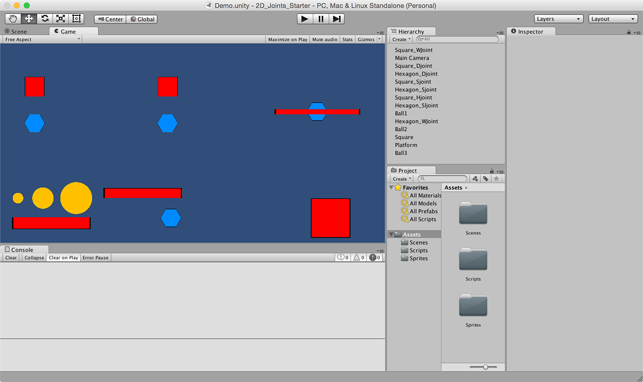
This scene contains various objects with physics components, much like you might find in any game. However, none of these shapes are connected by joints. Throughout this tutorial, you’ll get to try out each of Unity’s 2D joint types to see how they work.
Play the scene; you’ll see some of the objects immediately fall to earth due to the effects of gravity:

Note: While the labels in this scene are in fixed positions, the movement of the objects is based on the size of your Game view. For best results, put your Game view in Free Aspect mode and adjust its size in the Unity GUI until the objects and labels appear similar to the above image.
Note: While the labels in this scene are in fixed positions, the movement of the objects is based on the size of your Game view. For best results, put your Game view in Free Aspect mode and adjust its size in the Unity GUI until the objects and labels appear similar to the above image.
It’s time to get these objects working together with joints!
Distance Joint 2D
The first joint you’ll add – the Distance Joint 2D – has a very basic goal: to keep two objects separated by a constant distance. You’ll test this out on the red square and blue hexagon in the upper left of the scene.
Select Hexagon_Djoint in the Hierarchy and add a Distance Joint 2D Component to it, as shown below:

As you can see in the following image, this new component has several parameters that you can adjust to produce the best result for your game:

Fear not — you’ll soon learn what all these these parameters do and how you can adjust them.
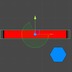
You’ll notice that once you have the component attached to the Hexagon that a green line extends from the Hexagon to the center of the screen. This is the origin point (0,0).

Run the scene, keeping your eye on the Hexagon.
Right away, you’ll notice that the Hexagon flies across the screen until it stops near the origin point, then begins to rock back and forth on the joint. The rocking behavior is the actual joint behavior, but what’s the deal with the initial jolt of energy? This is actual expected behavior and you’ll learn about it soon.
Turn your attention back the component in the Inspector. The Distance Joint 2D’s first parameter is Collide Connected. This determines whether or not the two objects connected by the joint can collide with each other. In this case, you don’t want this to happen, so leave it unchecked.
The second parameter is Connected Rigid Body. While one end of the distance joint always remains connected to the object that contains the component, you can use this field to pass a reference to an object for the other end of the joint’s connection. If you leave this field empty, Unity will simply connect the other end of the joint to a fixed point in the scene.
You want to connect Hexagon_Djoint to Square_Djoint in this case, so drag Square_Djoint to the Connected Rigid Body field:

With the connection set up and Hexagon_Djoint still selected, you should now see the two objects connected by the joint in the Scene view as follows:

The next parameter is Anchor, which indicates where the end point of the joint attaches to the GameObject as specified in the object’s local coordinate space. In the Scene view, with Hexagon_Djoint selected, you can see the anchor point as an unfilled blue circle centered over Hexagon_Djoint in the image above In this case, leaving the value at (0, 0) is fine.
Note: The unfilled blue circle representing the joint’s first anchor point may appear filled if you currently have the Transform tool selected in the Scene view. Likewise, you will see a white square if you have the Scale tool selected. In either case, moving the anchor away from (0, 0) will show that it is indeed an unfilled circle.
Note: The unfilled blue circle representing the joint’s first anchor point may appear filled if you currently have the Transform tool selected in the Scene view. Likewise, you will see a white square if you have the Scale tool selected. In either case, moving the anchor away from (0, 0) will show that it is indeed an unfilled circle.
The Connected Anchor parameter specifies the anchor point of the other end of the joint. If the Connected Rigid Body field is empty, this value is in the scene’s coordinate system. However, when Connected Rigid Body is set, as it is now, the Connected Anchor coordinates refer to the connected rigid body’s local coordinate space. This anchor point appears in the above image as a solid blue circle centered over Square_joint. Once again, you can leave this value at (0, 0).
The fifth parameter of the Distance Joint 2D is the one that bears its namesake: Distance. The name says it all: this parameter indicates the distance to maintain between both objects.
Back in the Scene view, you can see a small green line intersecting the line connecting the two objects; you can see this in the image below.

This line indicates the distance enforced by the joint. When you run the scene, the joint will move Hexagon_Djoint so that the Anchor you defined is at the point where the small line. As you increase or decrease, the line will correspondingly move up or down.

To give you a bit more room to see the joint in action, set Distance to 2, as shown below:
The last parameter is Max Distance Only. If enabled, the joint will only enforce a maximum distance, meaning that the objects can get closer to each other, but never further away than the value specified in the Distance field. In this example, you want the distance to be fixed, so leave this parameter disabled.
Run the scene and you should see that the hexagon attached to the square no longer falls from the scene:
While that’s sort of helpful, joints really only shine when one or more of their connections are moving. The project contains a helpful script that lets you drag objects with your mouse. Select Square_Djoint in the Hierarchy and drag Movement from the Scripts folder to the Inspector, as demonstrated below:

Run the scene; drag Square_Djoint around with your mouse to see your joint in action:

While you can see your joint working, you can’t actually see your joint. Sure, the Scene view shows a green line connecting the two objects, but the Game view doesn’t.
To get a better understanding of what’s happening, the project includes a script that renders a line between two objects at runtime. To visualize the joint, select Square_Djoint in the Hierarchy and drag Line from the Scripts folder to the Inspector:

Next, tell the Line script where to draw by dragging Square_Djoint and Hexagon_Djoint to Game Object 1 and Game Object 2 in the Inspector, as shown below:
Play your scene; you’ll see a line connecting the two objects:
Note: The Line script draws a line between the positions of two GameObjects. It doesn’t actually use the joint’s data, and as such, will not faithfully reproduce some joint settings. For example, if your distance joint does not specify a Connected Rigid Body, or if the anchors are not at (0, 0), then the line displayed will not properly visualize the joint’s location.
Note: The Line script draws a line between the positions of two GameObjects. It doesn’t actually use the joint’s data, and as such, will not faithfully reproduce some joint settings. For example, if your distance joint does not specify a Connected Rigid Body, or if the anchors are not at (0, 0), then the line displayed will not properly visualize the joint’s location.
You’ll notice that no matter where you move the Square_Djoint, the Hexagon_Djoint will always be a certain distance from it. Run your scene again, only this time check the Max Distance Only property of the Distance Joint 2D. This will only enforce the max distance of the joint, allowing the two objects to pass through each other. Now when you you move the Square_Djoint, you’ll see a different behavior.
Now that you’ve covered the Distance joint, the next logical step is to investigate Springs.